Read a Button and Drive an LED with ESP32 GPIO
By admin
A button and an LED are enough to learn how an ESP32 senses and controls a circuit. Build the input and output separately, then join them in software. Your first goal is to make an LED change state once per confirmed button press, even if you hold the button down.
Wire the two circuits
With power disconnected, connect a push button between an exposed GPIO25 and ground. Configure the input with an internal pull-up. An open button reads high and pressing it connects that pin to ground, producing an active-low signal. Confirm the pairs of contacts on a four-leg tactile switch with the continuity mode on a meter. Some legs are joined internally and can make a mistaken connection appear permanently pressed.
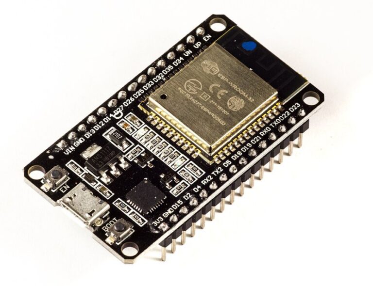
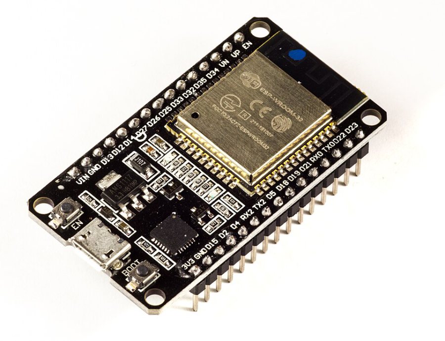
For the output, connect GPIO26 through a 470 ohm resistor to the anode of a common indicator LED and connect the cathode to ground. Confirm the resistor is in series before applying USB power. Configure the pin as an output and try turning the LED on and off from a basic example first. Both GPIO numbers assume a classic 30-pin board with the pins exposed. Review the header labels before connecting anything.
Separate the electrical state from the button action
Mechanical contacts may bounce during a press or release. The raw input can change several times before settling. Poll it regularly and start a timer each time the raw reading changes. Accept a new stable state when the reading has stayed the same for around 25 milliseconds, then adjust that interval using your own switch. Toggle the LED only on the transition to the confirmed pressed state. The stable release prepares the program for the next press.
Check the result
- Use the serial monitor to print the raw and confirmed states during setup.
- Tap the button several times, then hold it for two seconds. The LED should toggle once per press.
- Move one jumper at a time if the behavior differs from the diagram.
- Reset with the button released and check that the LED starts in a known state.
On the original ESP32, GPIO34 through GPIO39 can receive input and need an external resistor when the circuit requires a pull-up or pull-down. Keep loads beyond a small indicator LED on a suitable driver circuit.