How to Identify the Coil Pairs on a Four-Wire Stepper Motor
By admin
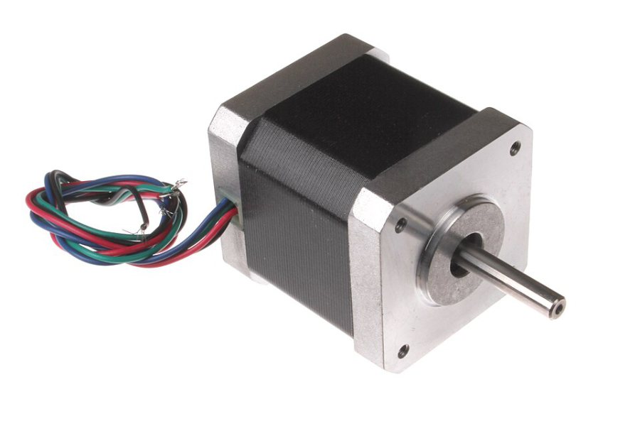
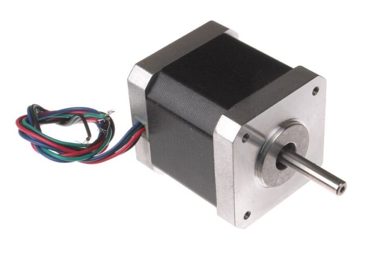
A four-wire bipolar stepper motor has two winding pairs. A bipolar driver energises one complete winding through each of its two output channels. If a cable places one wire from each winding on the same channel, the motor can vibrate without turning reliably. A few resistance measurements with the motor disconnected can map the wiring before you power the printer.
Make a resistance map with the motor isolated
Turn the printer off, disconnect its power sources and follow the manufacturer’s instructions before opening a controller compartment. Unplug the motor from the driver. Keep the meter in resistance or continuity mode, with the black and red leads in the meter jacks intended for that mode. Work on the disconnected motor leads only.
Temporarily label the wires 1 to 4 if their colours are ambiguous. Keep the shaft still while you measure. Pick wire 1 and measure to the other three. One pair should show a stable, finite winding resistance. Leads from the separate winding should read open. The remaining two wires should show a second finite resistance when measured together. If you get an inconsistent result, check the probes and cable contacts before drawing conclusions.
Trace the connector as well as the motor
As an example, if 1 to 3 measures a winding and 2 to 4 measures the other, label them A and B respectively. Check the driver diagram for the corresponding output pair on each phase. Follow the wires from the motor connector to the driver connector, since a harness can change the order between its ends. Compare your sketch with the printer’s wiring documentation.
Resistance identifies the winding pairs. The order within a pair also affects the direction of travel. Use the firmware’s direction setting if your printer documents that adjustment, or follow the wiring instructions for your driver and motor with power isolated.
Do a short, controlled test
- Reconnect the verified cable with the machine off.
- Start with a slow move from a position clear of the frame. Keep hands away from the mechanism.
- Confirm the axis moves in the expected direction before homing.
- Stop and check the mapping if the motor chatters, stalls or moves erratically.
This pairing method is for four-lead motors. For five, six or eight leads, consult the exact motor documentation before choosing a connection scheme.