Find an I2C Sensor with Your ESP32
By admin
With I2C, a sensor and an OLED display can share two signal wires. The bargain is that each module needs a compatible voltage, a distinct address and a clean bus. Start with a single peripheral so the first failure has only a few possible causes.
Build a known connection
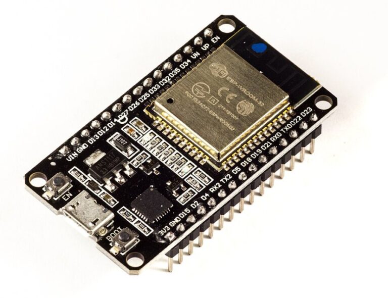
On a generic ESP32, Arduino commonly defaults to GPIO21 for SDA and GPIO22 for SCL. Verify that both headers exist and configure the actual pins in your program. Connect the grounds, then connect the module to the supply its board specifies. Test the signal levels and make sure both lines are pulled up to a voltage suitable for the ESP32. Some breakout boards include pull-up resistors wired to their supply. A board can accept 5 V power and still require an interface for its I2C signals.
SDA and SCL use open-drain signaling, which lets devices pull the lines low and release them to return high through the pull-ups. With power applied and the bus idle, both lines should normally read high. Use short leads and a 100 kHz bus while troubleshooting. Check the breakout documentation before adding more resistors, since multiple pull-up pairs add in parallel.
Use an address scan to narrow the problem
- Start the I2C controller on the selected SDA and SCL pins.
- Run a basic scanner that probes standard 7-bit addresses and records acknowledgements.
- Compare the reported address with the device documentation and any address jumper.
- Run a library example on that address and check one measurement before connecting more devices.
An acknowledgement confirms that something answered. It takes a successful measurement to establish that the sensor and library match. If there is no answer, check power, common ground and swapped SDA and SCL leads before changing libraries. If a line stays low, disconnect the module with power off and repeat the idle-voltage check after restarting.
Add the next device deliberately
Write the address on a label or in your project notes. If two peripherals use the same fixed address, consider another supported address, a separate bus or an I2C multiplexer. Rescan and read both devices after each addition. Test with the final wire length and again after a full restart, while the wiring is still accessible.