Choosing a NEMA 17 Stepper Motor for Your DIY 3D Printer
By admin
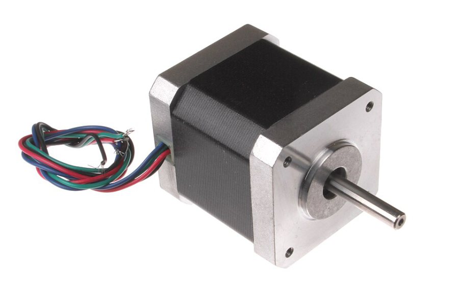
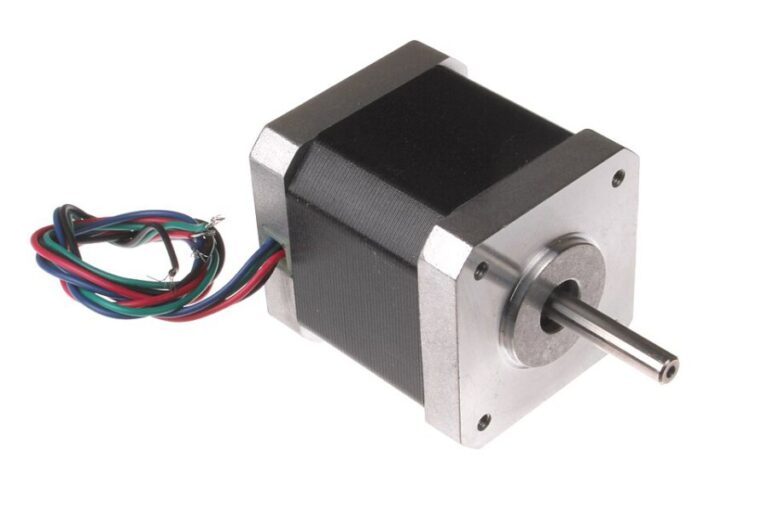
Two NEMA 17 motors can bolt into the same bracket and behave very differently. The designation identifies a mounting frame, typically described as roughly 42 mm across. The motor’s depth, shaft, step angle and electrical limits come from the individual model. Before ordering a replacement, write down the label on the existing motor and photograph how the pulley and cable are installed.
Check the mechanical fit first
Use the supplier’s dimensional drawing to compare the mounting holes and locating boss. Measure the clearance behind the bracket in every position the axis can reach. A deeper motor can interfere with a frame member, panel or cable even when the mounting pattern matches. Compare the shaft diameter, exposed length and flat with the existing pulley or coupling. The belt needs to line up with its idlers once the pulley is tightened.
Read the electrical nameplate
Find the current rating per phase and match the motor’s winding type to the driver. A common four-wire bipolar motor has two separate windings. Connector shells can look the same while their pin orders differ. Use the diagrams for both parts and check the cable end to end with the power off. The driver must support the required phase current under its actual cooling conditions.
Compare the step angle too. A 1.8° motor has 200 full steps per turn. A 0.9° motor has 400. If you replace one with the other while retaining the same transmission, the firmware configuration has to reflect the changed step count. The drive train’s travel per revolution stays the same.
Judge torque where the axis runs
Holding torque describes a stationary, powered motor under specified conditions. If you are changing the design instead of matching a known replacement, use the torque-versus-speed information for the intended drive conditions. Consider the moving mass, target acceleration, pulley size and whether a motor on the moving assembly adds weight. For an extruder, also check the gear ratio and available mounting space.
Replacement checklist
- Match the mounting face, body depth and shaft.
- Check winding type, connector pinout and current per phase.
- Confirm the step angle and keep a copy of the current firmware settings.
- Test short, slow moves after reassembly and check that cables stay clear throughout travel.