Use ESP32 PWM for Smooth LED Dimming
By admin
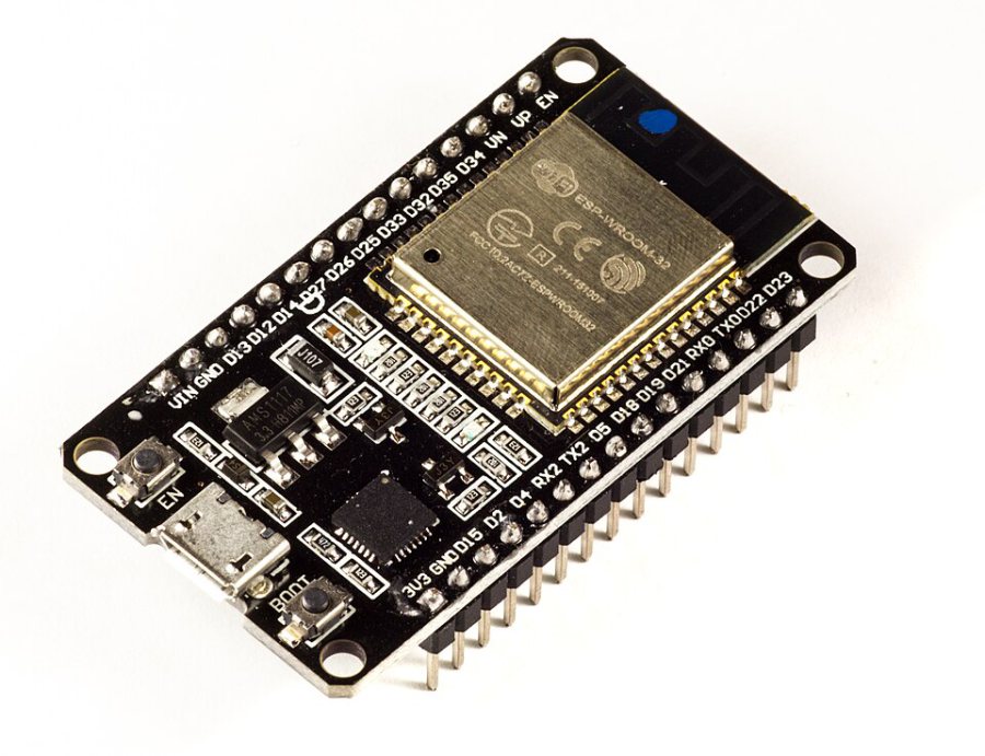
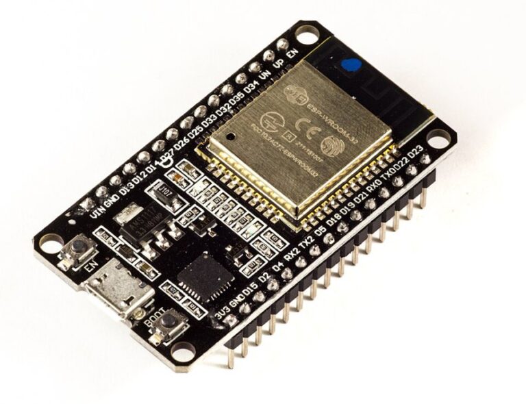
An LED can appear dimmer when an ESP32 switches it on and off rapidly. Pulse-width modulation, or PWM, changes the proportion of time spent on in each cycle. You can use that trick to build an adjustable indicator that fades gently and still leaves the processor free for other work.
Start with a single indicator
Use an exposed output-capable GPIO and connect a standard indicator LED in series with a suitable resistor. In a simple 3.3 V bench test, a 470 ohm resistor and a common red LED provide a modest starting load. Connect the cathode to ground. Confirm the GPIO and LED polarity before powering up. An LED strip, motor or high-power lamp needs a correctly rated driver and supply. Use the ESP32 output as the control signal for that circuit.
Set frequency and resolution together
Espressif calls the PWM peripheral used for this exercise LEDC. A timer sets the frequency and resolution, while a channel drives an assigned output. The achievable resolution depends on frequency and the clock configuration. Follow the documented API for your installed Arduino-ESP32 or ESP-IDF version, since examples for older libraries may use different function signatures. Check the return status when attaching a channel.
Try a 1 kHz frequency and 8-bit resolution for the indicator. Test duty values such as 0, 16, 64, 128 and 255. Observe how the light changes and check the output with an oscilloscope if one is available. A meter can show a rough average on a basic output, but its reading varies with the meter and waveform.
Build a fade you can repeat
- Begin with the LED off and increase the duty value over a fixed interval.
- Pause briefly near several low duty values to see where the LED becomes visible.
- Reduce the duty again and make sure the slight load has no effect on your board’s startup.
- Add your other outputs one at a time and check for unintended frequency changes on channels sharing a timer.
Equal numerical steps may appear uneven to the eye. Start with smaller changes around the bottom of the range and larger steps near the top if the indicator jumps in brightness. For a device that will appear on camera, review a recording under the actual lighting conditions and look for flicker or bands.