Bring Your 30-Pin ESP32 DevKit to Life
By admin
A 30-pin ESP32 DevKit can run a sensor, display or small automation project from a USB connection. The quickest route to a working board is to prove power, USB data and a serial upload before connecting any external circuit. That baseline saves time when you add a sensor and something stops working.
Identify the board on your desk
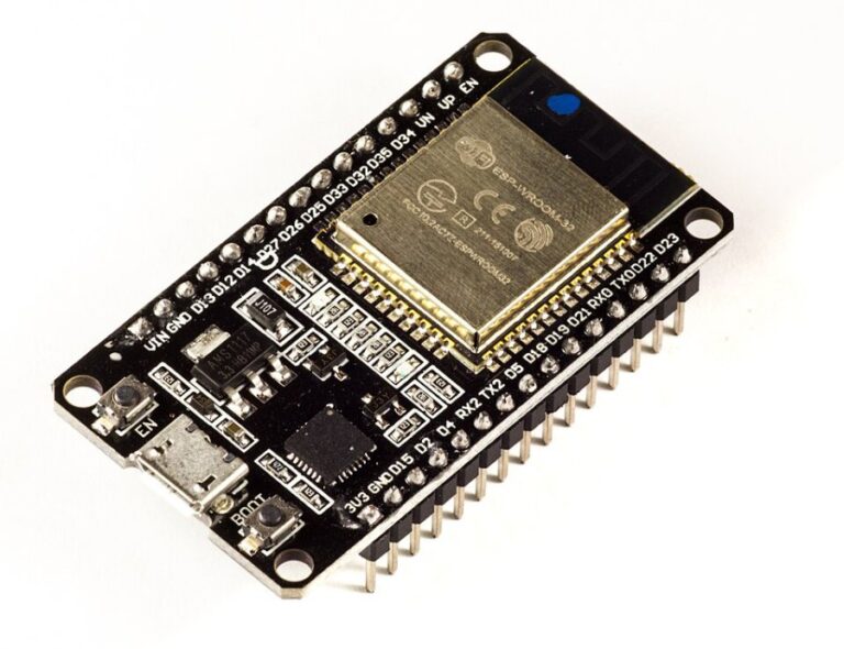
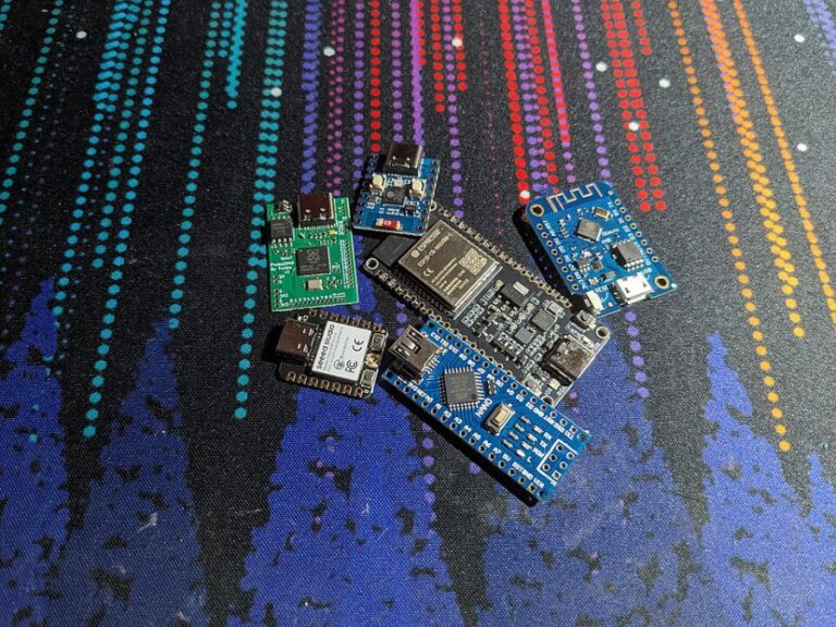
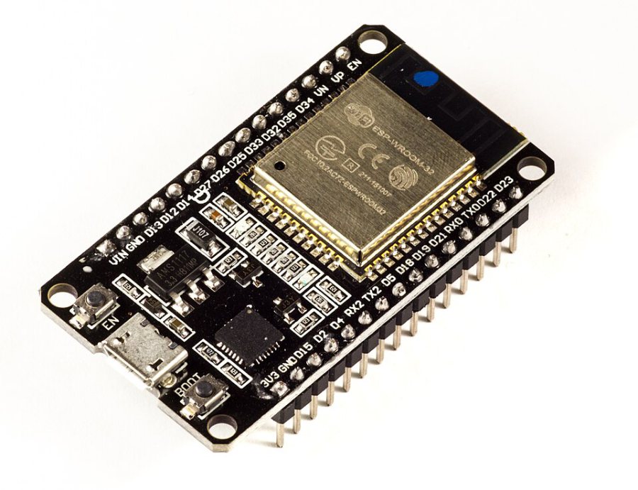
Read the marking on the metal radio module and write down the labels printed along the headers. Boards sold as 30-pin ESP32 DevKits can use different USB interfaces and header layouts. Match a pinout to the markings on your actual board. Espressif’s DevKitC guide explains the common parts of a development board, including the module, USB serial interface, reset and boot controls. Use the board seller’s diagram for the exact header order.
Prove the USB and serial path
- Connect the board using a USB cable you know carries data. Keep the header pins clear of conductive surfaces.
- Install Espressif’s Arduino-ESP32 platform through Boards Manager, or select the corresponding target in ESP-IDF.
- Select the board profile and the serial port that appears when you plug the board in. Upload a small sketch that prints a line once per second.
- Open the serial monitor at the baud rate set in the sketch. Press reset and check that the output starts again.
If the board powers up but no port appears, try the cable and a different USB port first. Identify the board’s USB interface before installing any driver. If the port opens but an upload fails, close any other program using it and check the board’s BOOT and reset procedure.
Choose pins with the next feature in mind
Treat GPIO on a classic ESP32 as 3.3 V logic, including boards with a 5 V power pin. GPIO34 through GPIO39 are input-only on the chip and lack internal pull resistors. Some pins affect startup, and some are used by flash, so review the pin restrictions before wiring. GPIO25 and GPIO26 are convenient candidates for a small digital test when both are exposed on your board.
Keep a short wiring note with the board profile, GPIO numbers, supply voltage and working serial settings. Add one peripheral at a time and rerun the baseline after each wiring change.