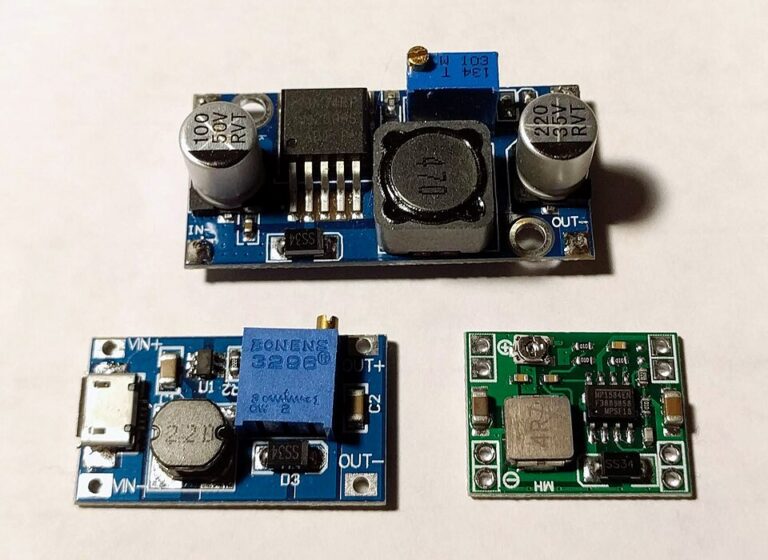
Measure LM2596 Output Ripple Without Chasing Probe Noise
By admin
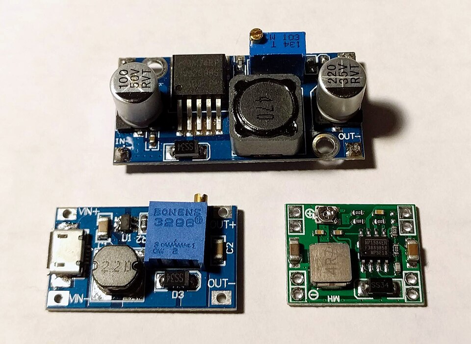
A multimeter can show a steady 5.0 V even when a switching converter’s output has small, fast variations. An oscilloscope reveals these variations, including recurring ripple and brief dips when a load switches on. Probe placement matters because a long ground lead can pick up switching noise and make spikes appear larger than they are at the output terminals.
Take a repeatable measurement
- Run the converter from a known low-voltage DC source. Identify the output ground and confirm that you can safely connect it to the oscilloscope ground. A conventional bench oscilloscope’s probe ground is typically tied to protective earth. Never clip it onto a switching node or a point that cannot be grounded.
- Use a compensated probe and the shortest practical ground connection. A compatible ground spring lets you measure directly across the output capacitor if its terminals are accessible safely. Turn off power while arranging clips or repositioning the setup.
- Start with DC coupling to confirm the rail voltage. Then use AC coupling and a finer vertical scale to inspect small variations. Record the scope bandwidth setting and load so you can reproduce the measurement.
- Measure with a steady load and then observe how the rail responds when the project’s demand changes. Check again at the project terminals if the converter is connected through long leads.
Connect the trace to the project
The LM2596 switches at a nominal 150 kHz, so an approximately repeating feature near that rate under steady operation can help identify switching ripple. A dip that follows relay actuation or another abrupt load change points toward transient behaviour. If changing the probe ground lead changes the observed spikes dramatically, recheck with a short connection before making changes to the board.
Review the converter datasheet before choosing replacement capacitors. Capacitance, equivalent series resistance and ripple current all matter in switch-mode supplies. For a remote load, shortening the supply and return path may help with voltage drop and pickup. Judge the final result against the powered device’s voltage and noise requirements, and save a trace with the intended load connected. That trace gives you a baseline for later changes to wiring, enclosure or power source.