Use a Relay Module to Switch a Low-Voltage DC Load
By admin
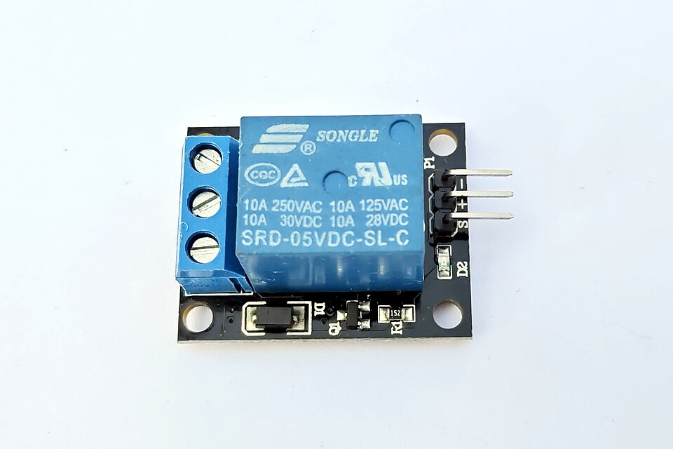
A relay module lets a microcontroller switch a separate low-voltage load circuit. The relay’s coil moves a set of contacts. The module’s input circuit determines how a controller commands that movement. A reliable first project is a small DC lamp with a documented voltage and current. Check the module’s control supply, input logic and DC contact rating before connecting the lamp.
Understand the contacts before wiring
With the relay coil off, COM is normally connected to NC and separated from NO. When a common changeover relay operates, COM disconnects from NC and connects to NO. With all power disconnected, check this arrangement against the board markings and confirm the resting contacts with a continuity meter. Decide whether the lamp should default to off or on when the relay releases. For a lamp that defaults to off, use COM and NO.
Connect the low-voltage load supply positive to COM. Connect NO to the lamp’s positive terminal if it has a required polarity. Connect the lamp’s return to the load supply negative. Follow the module documentation for its input supply and ground connections. Some inputs are active low and some are active high. Check whether your controller’s logic voltage can operate the module and what happens while the controller boots or resets.
Choose ratings for the actual load
Read the manufacturer’s DC ratings for the contacts at your supply voltage. A large AC ampere rating on a relay case cannot establish suitability for a DC load. Consider inrush current and load type. A DC motor or solenoid can create a voltage spike when switched off, so choose a suitable suppression method for that specific load. A flyback diode across a unidirectional coil or solenoid has its cathode toward positive during normal operation. Check polarity and whether the added release delay is acceptable.
Before connecting the final load, power the relay control side and verify that the expected command changes the contacts. If you are using a bare relay, select a suitable coil driver and suppression circuit. With the load connected, command on and off, reset the controller and cycle its power. Watching the lamp during all three checks helps identify an unwanted startup pulse while you still have a simple test circuit.