Get Consistent Analog Readings from an ESP32
By admin
When an ESP32 reports a jumpy analog reading, the source can be its wiring, configuration, noise on the supply or the signal itself. Begin with a voltage you can measure independently. Once the readings behave predictably, connect the real sensor and keep the same checks in place.
Choose a channel and check the voltage
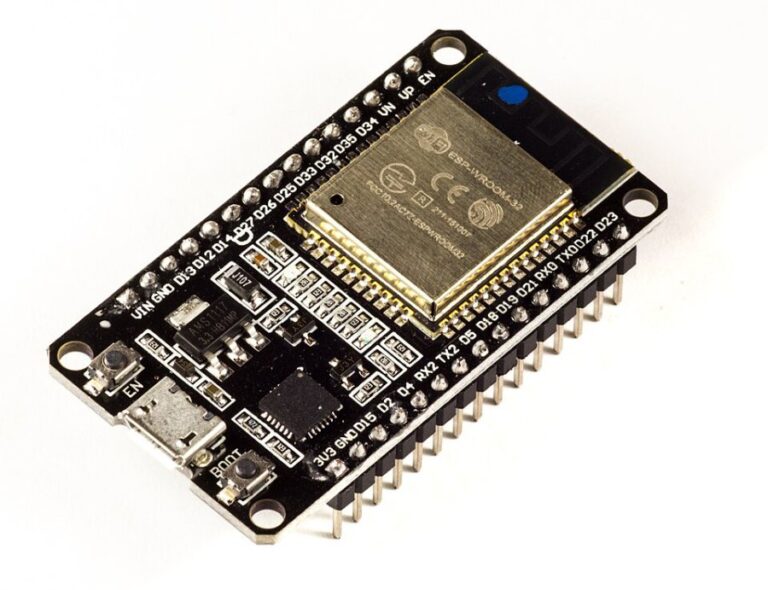
An original ESP32 running Wi-Fi should use an ADC1 channel for ordinary analog sensing. GPIO34 is one example when exposed on your development board. It is an input-only pin. Share ground between the source and ESP32 and make sure the analog input stays within the device’s electrical limits. A module powered from 5 V can present a signal that needs a divider or a suitable interface. Measure the signal and check the circuit specifications before attaching it.
In Arduino-ESP32, analogRead() delivers a raw ADC value and analogReadMilliVolts() reports a calibrated millivolt estimate. The attenuation setting affects the usable input range. Pick it using Espressif’s table for your chip rather than assuming that the maximum raw count represents precisely 3.3 V. Readings close to either end of the usable range can be particularly unhelpful for characterizing a sensor.
Run a three-point bench check
- Use a stable, voltage-limited source and begin at a modest level within the chosen range.
- Measure the actual voltage at the ESP32 pin with a multimeter while recording several ADC readings.
- Repeat at two higher levels within range. Note whether the measurement has a consistent offset, the wrong scale, large scatter or clipping.
- Run the same test with Wi-Fi active if networking is part of the finished project.
Keep analog leads short. Check the ground connection and supply when the signal changes alongside activity elsewhere on the board. A small group of readings averaged over time can tame random variation for a slowly changing measurement. It will also smooth changes you may want to observe, so compare raw and averaged values before selecting a sample count.
Log the conditions with the result
Record the ADC channel, attenuation, sampling interval and meter reading. For a sensor threshold, measure both sides of the intended trigger and allow for normal variation. Then revisit the threshold with the actual sensor attached so your calibration reflects the complete circuit.